Courses & Projects by Rob Marano
ECE 251: Week 08 Notes - Floating-Point Architecture
Overview
This week we transition from Chapter 2 (Instructions) directly into Chapter 3 of our textbook (Computer Organization and Design). Until now, we have exclusively designed hardware and processed data using the Integer Data Type (both signed and unsigned formats).
However, real-world engineering requires processing fractional decimal values. In these notes, we explore how computer architecture mathematically structures decimals, the limitations of Fixed-Point logic, the globally standardized IEEE 754 Protocol, and how MIPS manages these complex numbers using an external Floating-Point Unit (FPU) known as Coprocessor 1.
1. The Decimal Dilemma: Fixed vs. Floating Point
Our fundamental architectural issue is that physical memory arrays and CPU registers (like $t0) are rigidly built using 32 physical bits. How do we represent a decimal point . using only binary 0s and 1s?
The Fixed-Point Approach (And Why It Fails)
The most intuitive approach is to statically define an arbitrary dividing line within our 32-bit constraint. For example, we could say the first 16 bits represent the whole integer number, and the remaining 16 bits represent the fractional decimal.
- Pro: Immediate hardware simplicity. Normal integer Addition (
add) works natively. - Con (The Fatal Flaw): Extreme range limitation. If we divide 32 bits evenly, the maximum macro-scale number we can compute is only $2^{15} - 1 = 32,767$, and our precision for micro-scale numbers is strictly capped. In physics or graphics rendering (like the Quake example from Week 07), we need the ability to compute astronomical distances and microscopic wavelengths simultaneously. Fixed-point simply lacks the dynamic range.
The Floating-Point Protocol (IEEE 754)
To solve this, the Institute of Electrical and Electronics Engineers ratified the IEEE 754 Standard in 1985. Instead of fixing the decimal in place, the hardware dynamically “floats” the decimal point based on scientific notation, maximizing both range and granular precision within the exact same 32 bits!
Standard Scientific Notation: $-1.234 \times 10^{5}$ Binary Floating Point Notation: $(-1)^{s} \times (1 + \text{Fraction}) \times 2^{(\text{Exponent} - \text{Bias})}$
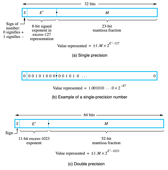
MIPS implements the Single Precision (32-bit) format utilizing three distinct, mathematically packed fields:
- Sign Bit (1 bit): Bit 31.
1is negative,0is positive. - Exponent (8 bits): Bits 30-23. Represents the $2^{\text{power}}$. (Uses a Bias of 127).
- Fraction / Mantissa (23 bits): Bits 22-0. The precise fractional magnitude.
When packed together, the CPU can dynamically reallocate its bit-budget: if the exponent is incredibly large, the number represents cosmic distances. If the exponent is incredibly negative, the exact same 32 bits represent microscopic fractions.
2. Hardware Segregation: Coprocessor 1 (The FPU)
Floating-point arithmetic (specifically multiplication and division) requires drastically different physical silicon gates to execute than standard integer math. Combining floating-point logic and integer logic into a single monolithic ALU would create massive, slow bottlenecks in the processor datapath.
Therefore, the MIPS architecture formally delegates all decimal math to a mathematically dedicated secondary chip known as Coprocessor 1 (CP1), universally referred to as the Floating Point Unit (FPU).
The FPU Register File
The FPU maintains its own separate, physically distinct memory array containing 32 independent registers ($f0 through $f31).
- Single Precision: Each register natively holds exactly 32 bits.
- Double Precision: The FPU pairs adjacent registers (e.g.,
$f0and$f1) to create massive 64-bit mathematical structures.
Specialized FPU Instructions
Standard MIPS instructions like add and lw cannot physically access the FPU. You must explicitly command the CPU to execute FPU-specific hardware commands. Notice they append .s (Single-Precision) or .d (Double-Precision) to the instruction.
- Loading/Storing:
lwc1 $f0, 0($a0)(Load Word to Coprocessor 1) - Arithmetic:
add.s $f0, $f1, $f2(Floating-Point Addition) - Moving Data:
mfc1 $t0, $f12(Move From Coprocessor 1 into Integer CPU)
F-Type (Floating-Point) Instruction Format:
opcode (6 bits) |
fmt (5 bits) |
ft (5 bits) |
fs (5 bits) |
fd (5 bits) |
funct (6 bits) |
|---|---|---|---|---|---|
| Instruction Class | Precision (.s=16, .d=17) |
Target Reg | Source Reg 1 | Dest Reg | Specific Math Operation |
$\Rightarrow$ For a complete execution list, refer to the “Floating-Point Instruction Formats” section on the back of your MIPS Green Sheet.
3. Representing Decimal Numbers: IEEE 754 Standard Deep Dive
(Synthesized from Patterson & Hennessy’s COaD and Hamacher’s Embedded Systems)
While the basic fields of IEEE 754 provide range and precision, the standard dictates several critical architectural details for reliable hardware evaluation:
- Biased Notation for Exponents: Unlike integer calculations which use Two’s Complement for negative numbers, the FPU exponent applies a Bias (+127 for Single Precision). Why? It purely simplifies hardware comparison logic. A biased exponent ensures that all exponent values remain strictly positive integers in binary, allowing the CPU to use a standard, high-speed integer comparator to check which floating-point number is larger.
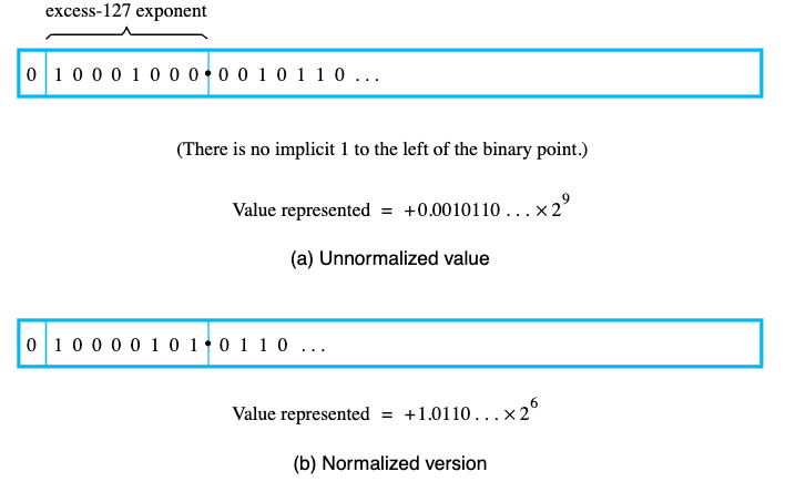
- Normalized Mantissas: The leading
1in the fractional component is always assumed (1.xxxxx). This “hidden bit” buys us one extra bit of free precision, granting 24 bits of effective accuracy in a 23-bit field.
- Architectural Special Values:
- Zero: Exponent =
00000000, Fraction =0 - Infinity: Exponent =
11111111, Fraction =0(Used for divide-by-zero). - NaN (Not a Number): Exponent =
11111111, Fraction $\neq 0$ (Used for illegal math, like taking the square root of a negative without complex logic).
- Zero: Exponent =
Textbook Examples: IEEE 754
Example 1: Easy (Decimal to IEEE 754 Single Precision) Problem: Convert $-0.75_ {10}$ to IEEE 754 Single Precision binary. (Source: COaD) Solution:
- Calculate the binary fraction: $-0.75_ {10} = -3/4 = -0.11_ {2}$.
- Normalize to scientific notation: $-1.1_ {2} \times 2^{-1}$.
- Field 1 (Sign): The number is negative, so Sign =
1. - Field 2 (Exponent): True exponent is $-1$. Add the bias: $-1 + 127 = 126$. Binary representation is Exponent =
01111110. - Field 3 (Mantissa): Drop the leading
1(hidden bit). The fractional remainder is just1. Pad with zeros: Mantissa =100 0000 0000 0000 0000 0000. Final 32-bit Code:1 01111110 10000000000000000000000(0xBF400000)
Example 2: Medium/Hard (Floating-Point Decimal Arithmetic) Problem: Convert $12.375_ {10}$ to IEEE 754 Single Precision. Solution:
- Define the whole number: $12_ {10} = 1100_ {2}$.
- Define the fraction: $0.375_ {10} = 3/8 = 0.011_ {2}$.
- Combine: $1100.011_ {2}$.
- Normalize: $1.100011_ {2} \times 2^{3}$.
- Calculate fields:
- Sign: Positive $\rightarrow$
0. - Exponent: $3 + 127 = 130 \rightarrow$
10000010. - Mantissa: Drop leading 1 $\rightarrow$
10001100000000000000000. Final 32-bit Code:0 10000010 10001100000000000000000(0x41460000)
- Sign: Positive $\rightarrow$
4. Literal Values in ISA Design
(Synthesized from Harris & Harris’ Digital Design and COaD)
A critical aspect of Instruction Set Architecture (ISA) design is how to handle Literals/Immediates—hardcoded numbers directly embedded into the code (e.g., addi $t0, $t0, 4 or li $v0, 10).
- Design Principle - “Make the Common Case Fast”: Statistical analysis of running programs shows that small constants (like
0,1,4) account for over 50% of arithmetic and branching operands. Instead of storing these constants in memory and executing an expensivelw(Load Word) operation every time, MIPS dedicates the I-Type Instruction Format to embed a 16-bit literal directly inside the 32-bit instruction. - The 32-bit Literal Workaround: To maintain ISA design principles like “Good design demands good compromises” and “Simplicity favors regularity” (keeping all instructions exactly 32 bits), MIPS cannot fit a 32-bit literal inside a 32-bit instruction. When a massive literal is needed, the architecture uses a two-instruction macro (often masked by the pseudo-instruction
li):lui $t0, 0x1234(Load Upper Immediate into the top 16 bits).ori $t0, $t0, 0xABCD(Bitwise OR the lower 16 bits).
Textbook Examples: Initializing Literals
Example 1: Easy (Base I-Type Arithmetic)
Problem: Compile the C-code A = B - 50 into a MIPS native instruction assuming A = $s0 and B = $s1. (Source: Harris & Harris)
Solution:
There is no subi instruction in MIPS. The architecture handles negative constants using standard addi.
Assembly: addi $s0, $s1, -50
Machine Encoding:
- Opcode (
addi):8$\rightarrow$001000 rs($s1):17$\rightarrow$10001rt($s0):16$\rightarrow$10000imm($-50_ {10}$ in Two’s Complement):1111 1111 1100 1110
Example 2: Medium/Hard (Loading a 32-bit Literal)
Problem: Load the enormous 32-bit hex address 0x003D0900 into integer register $s0. (Source: COaD)
Solution:
Because I-Type formats strictly limit immediate values to 16 bits, we cannot accomplish this in one clock cycle. We must use a two-instruction macro.
- Load the upper 16 bits (the left half) into the top of the register:
lui $s0, 0x003D(Loads0000 0000 0011 1101into the upper 16 bits, clears lower bits). - Splice the lower 16 bits (the right half) using Bitwise OR:
ori $s0, $s0, 0x0900(ORs0000 1001 0000 0000into the lower 16 bits). (Note: Attempting to useaddiinstead oforican fail here becauseaddisign-extends its 16-bit argument, potentially corrupting the explicit upper bit-pattern).
5. Instruction Definition and Hardware Implementation
(Synthesized from Harris & Harris and Cavanagh’s HDL Fundamentals)
How does the processor actually physically evaluate these instructions in SystemVerilog hardware?
- Microarchitectural Datapath: The physical datapath for integer instructions (like
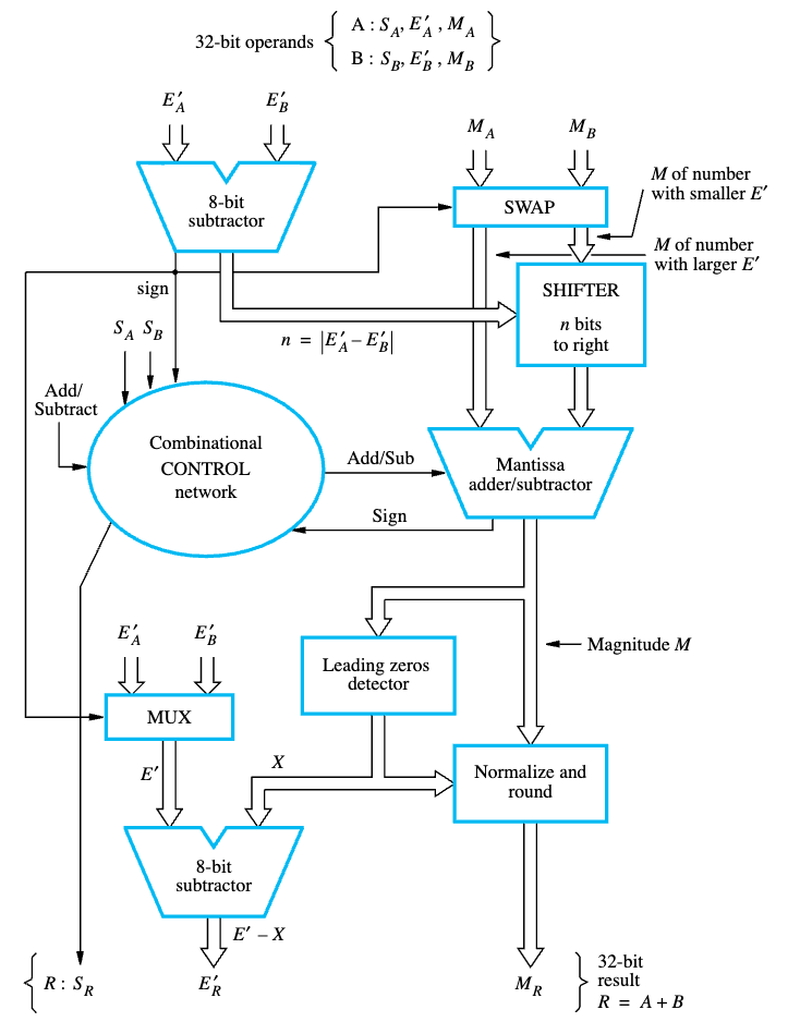
add) usually resolves in a single clock cycle utilizing a standard ripple-carry or carry-lookahead adder. Floating-point operations, however, require massive gate depth. The physical implementation of an FPU instruction mathematically requires distinct sequential processing states:- Alignment: Shift the smaller number’s mantissa to the right until both exponents match perfectly.
- Execution: Route the aligned mantissas through the fractional adder or subtractor.
- Normalization: Shift the resulting decimal back to regain the strict
1.xxxxleading format and adjust the exponent accordingly. - Rounding: Apply IEEE 754 rounding rules (Truncate, Round to Nearest Even, Round to +Inf, Round to -Inf).
- Verilog / FPU Bottlenecks: Because this 4-step hardware process involves significant transistor propagation delay, FPU adders and multipliers must be deeply pipelined in silicon. While an integer
addmay finish in 1 cycle, anadd.smight require 4 to 6 discrete clock cycles, and adiv.scould halt the pipeline for 20+ cycles. This constraint highlights precisely why Coprocessor 1 must be logically segregated from the main integer datapath—if they shared the exact same clock phase logic, the floating-point latency would catastrophically cripple the entire central processing unit’s throughput.
Textbook Examples: Hardware Implementation
Example 1: Easy (Tracing an Integer Datapath)
Problem: Trace the specific microarchitectural hardware units utilized during a complete clock cycle of the instruction add $t0, $t1, $t2. (Source: Hamacher / Harris)
Solution:
The integer addition requires precisely defined functional units in sequence:
- Instruction Memory: Fetch the instruction located at the Program Counter (PC).
- Register File (Read): Decode instruction. Extract operands simultaneously from read ports corresponding to
$t1and$t2. - ALU (Execute): The arithmetic logic unit evaluates
$t1 + $t2via its combinational gate datapath. - Register File (Write): Write the ALU result back into the register file on the falling edge of the clock cycle at address
$t0using the Write Data port. (Data Memory is entirely bypassed during an R-Type ALU operation).
Example 2: Medium/Hard (Tracing a Coprocessor 1 FPU Pipeline)
Problem: Detail the sequential hardware logic utilized by the FPU to execute add.s $f0, $f1, $f2, highlighting why it cannot execute in a single basic clock cycle. (Source: Cavanagh HDL / COaD)
Solution:
 Attempting $0.5 + (-0.4375)$ requires the FPU to perform multi-stage calculations that drastically exceed integer ALU latency.
- Exponent Comparison & Alignment Shift: The hardware unpacks the 8-bit exponents. It finds
$f1’s exponent is $2^{-1}$ and$f2is $2^{-4}$. The smaller number ($-0.4375$) must be shifted dynamically to the right by 3 places so both numbers share the $2^{-1}$ power frame. - Fraction Addition: Only once aligned can the 24-bit Mantissa ALU process the math.
- Normalization Shift: The result might have spawned a carry or absorbed a leading
1. The hardware must shift the solution left/right until the leading1is perfectly normalized (1.xxxx), while simultaneously decrementing/incrementing the resulting Exponent field. - Rounding Hardware: The IEEE 754 logic ensures the trailing fractional bits are properly truncated or rounded to nearest even. Because no silicon can propagate these cascading tests and shifts instantaneously, FPUs must pipeline this operation, dividing it across 4 to 6 unique clock cycles to avoid crashing the CPU max clock frequency.
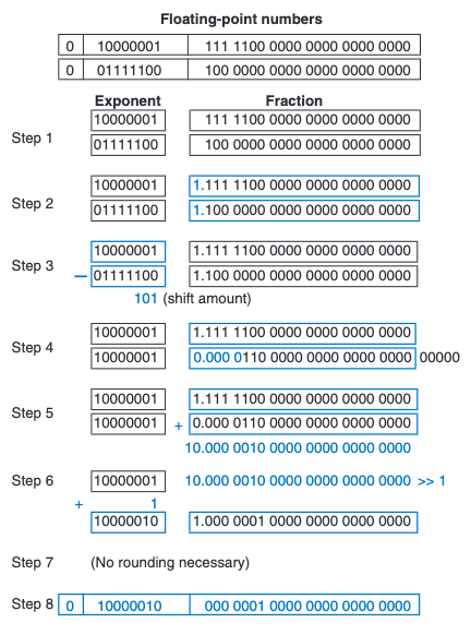
(For an explicit binary step-by-step logic trace of this execution pipeline, analyzing the alignment and addition of $7.875_{10} + 0.1875_{10}$, see Figure 5.29 below):
Appendix: Additional Floating-Point Exercises
Exercise 1: Easy (Decimal to Single & Double Precision) Problem: Convert $8.5_ {10}$ to IEEE 754 Single-Precision (32-bit) and Double-Precision (64-bit) binary formats. Solution:
- Calculate the binary fraction: $8_ {10} = 1000_ {2}$ and $0.5_ {10} = 1/2 = 0.1_ {2}$. Thus, $8.5_ {10} = 1000.1_ {2}$.
- Normalize to scientific notation: $1.0001_ {2} \times 2^{3}$.
- Field 1 (Sign): The number is positive, so Sign =
0. - Single Precision (32-bit):
- Exponent: True exponent is $3$. Add the Single bias (+127): $3 + 127 = 130 \rightarrow$
10000010. - Mantissa: Drop the leading
1. The fractional remainder is0001. Pad with zeros to 23 bits $\rightarrow$0001 0000 0000 0000 0000 000. - Final 32-bit Code:
0 10000010 00010000000000000000000(0x41080000)
- Exponent: True exponent is $3$. Add the Single bias (+127): $3 + 127 = 130 \rightarrow$
- Double Precision (64-bit):
- Exponent: True exponent is $3$. Add the Double bias (+1023): $3 + 1023 = 1026 \rightarrow$
100 0000 0010. - Mantissa: Drop the leading
1. The fractional remainder is0001. Pad with zeros to 52 bits $\rightarrow$0001followed by 48 zeros. - Final 64-bit Code:
0 10000000010 0001000000000000000000000000000000000000000000000000(Upper:0x40210000, Lower:0x00000000)
- Exponent: True exponent is $3$. Add the Double bias (+1023): $3 + 1023 = 1026 \rightarrow$
Exercise 2: Medium (Negative Fractional Decimal) Problem: Convert $-0.15625_ {10}$ to IEEE 754 Single and Double Precision. Solution:
- Calculate the binary fraction: $0.15625_ {10} = 5/32 = 1/8 + 1/32 = 0.125 + 0.03125 = 0.001_ {2} + 0.00001_ {2} = 0.00101_ {2}$.
- Normalize to scientific notation: $-1.01_ {2} \times 2^{-3}$.
- Field 1 (Sign): The number is negative, so Sign =
1. - Single Precision (32-bit):
- Exponent: $-3 + 127 = 124 \rightarrow$
01111100. - Mantissa: Drop leading
1$\rightarrow$0100 0000 0000 0000 0000 000. - Final 32-bit Code:
1 01111100 01000000000000000000000(0xBE200000)
- Exponent: $-3 + 127 = 124 \rightarrow$
- Double Precision (64-bit):
- Exponent: $-3 + 1023 = 1020 \rightarrow$
011 1111 1100. - Mantissa: Drop leading
1$\rightarrow$0100followed by 48 zeros. - Final 64-bit Code:
1 01111111100 0100000000000000000000000000000000000000000000000000(Upper:0xBFC40000, Lower:0x00000000)
- Exponent: $-3 + 1023 = 1020 \rightarrow$
Exercise 3: Hard (Repeating Fraction & Rounding) Problem: Convert $0.1_ {10}$ to IEEE 754 Single and Double Precision. Solution:
- Calculate the binary fraction: $0.1_ {10}$ cannot be represented perfectly in binary. It is a repeating fraction: $0.0001100110011…\overline{0011}_ {2}$.
- Normalize to scientific notation: $1.100110011…\overline{0011}_ {2} \times 2^{-4}$.
- Field 1 (Sign): The number is positive, so Sign =
0. - Single Precision (32-bit):
- Exponent: $-4 + 127 = 123 \rightarrow$
01111011. - Mantissa: Drop the leading
1. We need the first 23 bits:1001 1001 1001 1001 1001 100. The incredibly strict IEEE 754 “Round to Nearest, Ties to Even” requires us to look at the 24th bit (which is a1). Since it’s a1, we must round up our 23-bit mantissa $\rightarrow$1001 1001 1001 1001 1001 101. - Final 32-bit Code:
0 01111011 10011001100110011001101(0x3DCCCCCD)
- Exponent: $-4 + 127 = 123 \rightarrow$
- Double Precision (64-bit):
- Exponent: $-4 + 1023 = 1019 \rightarrow$
011 1111 1011. - Mantissa: We take the first 52 bits. Again, the 53rd bit causes us to round up the very last bit. The final field is:
1001100110011001100110011001100110011001100110011010. - Final 64-bit Code:
0 01111111011 1001100110011001100110011001100110011001100110011010(Upper:0x3FB99999, Lower:0x9999999A)
- Exponent: $-4 + 1023 = 1019 \rightarrow$
Exercise 4: Easy (IEEE 754 Binary to Decimal)
Problem: Convert the following 32-bit Single-Precision binary value (0x40D00000) into a base-10 decimal:
0 10000001 10100000000000000000000
Solution:
- Sign field:
0$\rightarrow$ The number is Positive$+$. - Exponent field:
10000001in decimal is $128 + 1 = 129$. Subtract the Single-Precision bias (127): $129 - 127 = 2$. Exponent is $2^{2}$. - Mantissa field:
101000.... Append the hidden leading1.: The scientific fraction is $1.101_ {2}$. - Combine: $+1.101_ {2} \times 2^{2}$.
- Shift the decimal: Move the point to the right by 2 to multiply: $+110.1_ {2}$.
- Convert binary to decimal: $(1 \times 4) + (1 \times 2) + (0 \times 1) + (1 \times 0.5) = \mathbf{6.5_ {10}}$.
Exercise 5: Medium (IEEE 754 Hexadecimal to Decimal)
Problem: In a debugger, register $f0 contains the hex value 0xC1480000. What base-10 decimal value does this represent?
Solution:
- Convert Hex to Binary:
Cis1100,1is0001,4is0100,8is1000. $\rightarrow$1100 0001 0100 1000 0000 0000 0000 0000 - Slice into Fields:
$\rightarrow$
1|10000010|10010000000000000000000 - Sign:
1$\rightarrow$ Negative$-$. - Exponent:
10000010is $128 + 2 = 130$. Minus bias: $130 - 127 = 3$. Exponent is $2^{3}$. - Mantissa: Add the hidden bit to
1001: $1.1001_ {2}$. - Combine & Shift: $-1.1001_ {2} \times 2^{3} \rightarrow -1100.1_ {2}$.
- Convert to Decimal: $-(8 + 4 + 0.5) = \mathbf{-12.5_ {10}}$.
Exercise 6: Hard (IEEE 754 Hexadecimal to Micro-Decimal)
Problem: MIPS memory contains 0xBED00000. Calculate its exact base-10 value.
Solution:
- Convert Hex to Binary:
B=1011,E=1110,D=1101,0=0000. $\rightarrow$1011 1110 1101 0000 0000 0000 0000 0000 - Slice into Fields:
$\rightarrow$
1|01111101|10100000000000000000000 - Sign:
1$\rightarrow$ Negative$-$. - Exponent:
01111101in decimal is $64 + 32 + 16 + 8 + 4 + 1 = 125$. Minus bias: $125 - 127 = -2$. Exponent is $2^{-2}$. - Mantissa: Add the hidden bit to
101: $1.101_ {2}$. - Combine & Shift: $-1.101_ {2} \times 2^{-2} \rightarrow$ Move decimal left by 2 $\rightarrow -0.01101_ {2}$.
- Convert to base-10 Decimal: $-(0 \times 0.5 \quad+\quad 1 \times 0.25 \quad+\quad 1 \times 0.125 \quad+\quad 0 \times 0.0625 \quad+\quad 1 \times 0.03125)$ $-(0.25 + 0.125 + 0.03125) = \mathbf{-0.40625_ {10}}$.
6. The Quake III Inverse Square Root: Exploiting IEEE 754
During Weeks 06 and 07, we observed the famous Quake III Arena Fast Inverse Square Root algorithm implemented in MIPS (quake_calc.s). Without understanding Chapter 3 and the IEEE 754 standard, the core logic appears to be pure sorcery.
Let us review the exact MIPS core logic utilized to approximate $\frac{1}{\sqrt{x}}$:
# Move float bits from FPU ($f12) into CPU Integer Register ($t0)
mfc1  $t0, $f12

# i = 0x5f3759df - ( i >> 1 );
srl   $t1, $t0, 1        # Bit-shift right by 1
lw    $t2, magic         # Load magic number (0x5f3759df)
sub   $t0, $t2, $t1      # Integer subtraction

# Move integer bits ($t0) back to FPU ($f0)
mtc1  $t0, $f0
How IEEE 754 Makes This Possible
Why does moving a floating-point number into an integer register, shifting its bits, and subtracting it from 0x5f3759df yield a phenomenally accurate first-pass approximation for $\frac{1}{\sqrt{x}}$?
The brilliance lies fundamentally in the IEEE 754 Exponent Bias and the Mantissa (Fraction) Normalization we just studied!
- Logarithmic Representation: By defining a floating-point number $x$ as $(1 + m) \times 2^{e}$, taking the log base-2 yields $\log_2(x) = \log_2(1+m) + e$. Because $m$ is constrained between 0 and 1, $\log_2(1+m) \approx m + \mu$ (where $\mu$ is a tuning constant). This means the raw 32-bit integer representation of the IEEE 754 float is essentially a scaled version of its own logarithm!
- The Mathematics of $\frac{1}{\sqrt{x}}$: Calculating an inverse square root is mathematically evaluating $x^{-0.5}$. In logarithmic space, this is simply multiplying the logarithm by $-0.5$.
- The Bit Shift (
i >> 1): In the raw integer representation, shifting bits right by one position is exactly calculating the division by 2 (the $0.5$ in $-0.5$). - The Magic Constant (
0x5f3759df): Because we must negate the exponent ($-0.5$) and correctly subtract the IEEE 754 bias offset (+127), we cannot simply subtract from zero. Mathematical derivation of the optimal bias error offset ($\mu$) combined with the bit-shifted IEEE 754 exponent bias geometrically yields the hex constant0x5f3759df.
By exploiting the physical 32-bit structure of IEEE 754, the programmer bypassed the massive latency of FPU division and square-root operations—performing a complex non-linear curve approximation using a single sub-nanosecond integer bit-shift (srl) and an integer subtract (sub)!